Drag and Drop
[NOTE: This tutorial is for meshmixer02. meshmixer03 works in a similar way, but with some changes. Click the little + sign to the right of the Tool Name bar in meshmixer03 to get in-app help.]
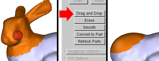
The meshmixer Drag and Drop tool allows you to select part of a mesh and drag it somewhere else, filling the hole left behind. To use the tool, first select a set of faces (see the Selection Tutorial for help on this). Then click the Drag and Drop button. The selection will disappear and be replaced with a fill surface, which fills the hole left behind when the part is cut off. See the Filling Tutorial for details on how to sculpt the fill surface.
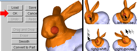
Once you are satisfied with your fill surface, click the OK button, or hit the a key ("accept"). The fill surface is welded to the mesh, creating the base mesh for the drag-and-drop operation. The part you initially selected will then re-appear, and you can move it across the surface by left-dragging. You can also rotate the part by right-dragging and if you shift+right-drag, you can scale the part. Once you are happy with the result, click OK or hit the a key to stitch the part into the base mesh.
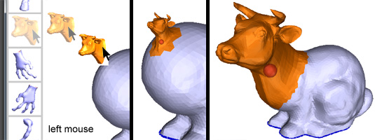
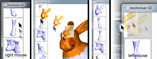
You can also drag-and-drop parts from your Part Library, the toolbar on the left side of the 3D viewport. Just left-drag the part onto the current mesh, position it, and click OK to stitch it in.
You can scroll the part library by right-dragging up and down, but you have to click down on top of the toolbar. You can add a part to the library by left-dragging it onto the part library toolbar, it will appear at the top of the list. And you can discard a part by dragging it to the left, out of the meshmixer window (clearly this won't work if the window is maximized).
Note that when you discard a part, the part file is gone for good! The undo operation currently doesn't affect the part library.
When you are in "drag-and-drop" mode - when a part is active on the base mesh - a set of parameters will appear in the right toolbar. These parameters have different effects on the part, depending on the Type setting. There are currently two drop types - COILS and RotInvCoord.
The main difference between the types is that COILS concentrates the part deformation near the boundary, so the interior is more rigid, while RotInvCoord tries to evently spread the deformation across the entire part. Usually COILS has a smoother transition at the boundary, but the interior is not as smooth as RotInvCoord. This non-smoothness is most noticeable if the part is highly deformed. Also, COILS can handle parts with interior holes.
[COILS Drop Type Parameters]
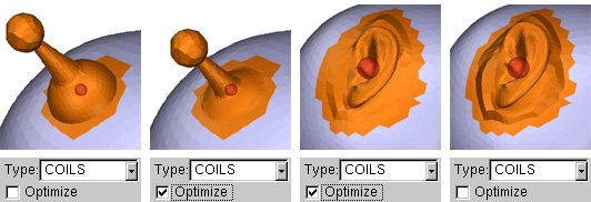
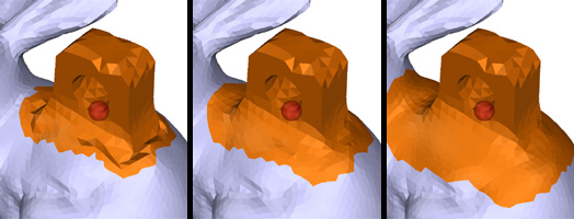
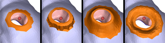
The Optimize checkbox determines whether meshmixer should try to enforce a smooth transition across the part boundary. Below two examples are shown - on the left is an antenna which has a hard edge, so Optimize is un-checked. If we check it, meshmixer will bend the part inward to produce a smoother transition. For the ear part, Optimize is checked because the part should smoothly blend in with the base mesh. If we un-check it, the ear will bulge outwards. Note that the optimization is computationally intensive, so if you want faster framerates, you can turn it off and tune the Bulge parameter yourself (see below).
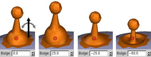
The Bulge parameter is an angle, and is used to locally rotate the surface inwards or outwards around the boundary polyloop. The Optimize checkbox automatically determines the Bulge setting that will maximize smoothness across the boundary. You can tweak it yourself to achieve a wide range of results - the example below show several settings on a sharp-edged part.
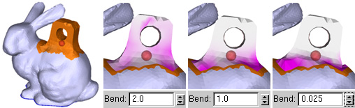
The Bend parameter controls how much the part conforms to the target surface. The default Bend value is 2, which allows the deformation to spread out a reasonable distance into the part. One problem with this is if you want to drop something that should be very rigid. In the example below, the circular hole is deformed, which is something we might like to avoid. So decreasing Bend will harden the part, pushing more of the deformation to the boundary. (Increasing Bend increases deformation towards the target surface shape, but it doesn't usually look very good...)
(In the images below, the purple coloring indicates areas of increased part deformation. Press the 8 key to toggle this visualization on and off when you are in drop mode. Note that this won't work if SmoothR is non-zero)
One problem with making a part more rigid using Bend is that the smooth transition at the boundary tends to get lost. You can recover the smooth transition by increasing the Smoothing Radius (SmoothR) parameter. This value is used to define a region surrouding the part which is automatically smoothed to create a soft blending transition, as shown below. Note that the smoothing region is not remeshed, so you can set it to be arbitrarily high without changing your topology.
Changing the Offset parameter causes the part be "pushed in" or "pulled out" of the target surface. This can be particularly useful if making the part rigid causes it to penetrate the surface in an unappealing way. The offset tool can also be used as a general deformation tool, as shown below.
The Scale parameter controls a non-uniform scaling factor. There is a smooth transition from a value of 1 at the part boundary to the value you set. This control can be useful if you want the part to be a certain size but it won't fit without an ugly boundary connection. Just globally scale it down (shift+right-drag) until there is enough room for the base, then increase Scale to get the rest of the part back to the size you want.
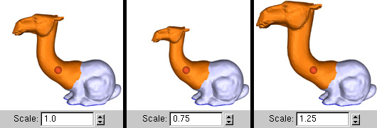
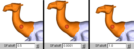
The Scale Falloff (SFallof) parameter controls the range of the smooth transition region for the Scale parameter. In the example below, Scale=0.75 (the middle image above). At the default value, SFalloff=0.5, the transition is complete about half-way along the part. As SFalloff gets closer to 0, the end of the transition moves towards the nose. If SFalloff is set to 1 the transition is very quick, and most of the part is uniformly scaled.
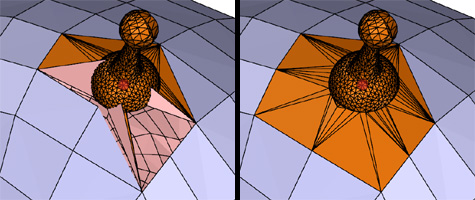
The Tweak Radius (TweakR) parameter should only be used if the drop operation fails. This mainly happens when there is a large difference between the size of the polys on the part and the size of the target polys, as in the example below-left. In this case, increasing TweakR will expand the region of the target surface that is remeshed, repairing the problem. You can also use TweakR to try to reduce the size of the remeshed region (ie preserve more of your topology). But beware, you can end up creating cracks if you make it too small.
[RotInvCoord Drop Type]
(The RotInvCoord drop type is currently experimental. Feel free to give it a try. You will find that it is not as smooth at the boundary, but is usually smoother on the part interior. It also tends to spread the total part deformation more evenly across the part, which might be desirable in some cases, and can result in increased part rigidity. But it will fail if your part has interior holes (like eye cut-outs), and it will sometimes jump around and do other wacky stuff)
[Part Manipulation Widgets]
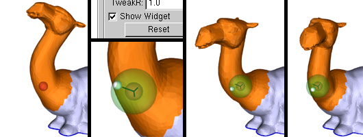
It often happens that the drop location that gives the nicest boundary transition will leave the part in some undesirable orientation. For example, in the image below-left, I would like the neck to be more vertical. By clicking on the Show Widget checkbox, or pressing the 0 key, a small orientation widget will appear at the base of the part (around the red sphere). To use this widget, click and drag on the white ball - it will be "stuck" to the spear, and the part will be deformed to point towards it. (You might want to check the result from a few different viewpoints!)