Making Your Own Parts
[NOTE: This tutorial is for meshmixer02. meshmixer03 works in a similar way, but with some changes. Click the little + sign to the right of the Tool Name bar in meshmixer03 to get in-app help.]
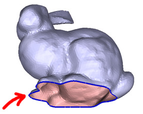
This tutorial is about manually creating your own parts. Ideally, you should be using parts created within meshmixer, by cutting them from other models. You really only need one strip of surrounding faces to cut a part. Take the example below. I selected a thin strip of faces, then right-clicked on the background to invert the selection. Now almost the entire head is selected. Click Drag-and-Drop, pick a nice fill surface, then drop the part into the library. Voila, bunny with a human head!
So, the only time you really need to create a part is when you can't even cut off a single strip of boundary triangles. You may also need to create a part if you want hard edges. If that's the case, this tutorial is for you.
You can't just thrown any old mesh into the \parts_default folder and expect it to work. There are several requirements that a part needs to meet if meshmixer is going to be able to drop it onto another surface. In meshmixer02, I added an interactive tool that will automatically create a part from a loaded mesh. If you really want to set up the part yourself, there is a meshmixer01 tutorial further down that will explain how to do that as well.
[meshmixer02]
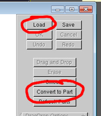
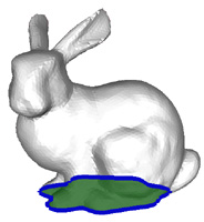
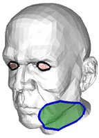
In meshmixer02, a special tool was added to create parts. To use this tool, first load the mesh you want to turn into a part. This mesh has to have at least one open boundary loop. The edges of boundary loops will be shown in blue. Once your mesh is loaded, click the Convert to Part button.
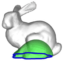
The surface will turn white, and the blue boundary loop will get thicker. A green surface will be shown over top of your mesh - this surface is the "fill surface" for the boundary loop (below right). Now you see how the part conversion works. Meshmixer literally fills in the boundary loop, and then cuts the mesh off of this new fill surface.
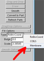
The shape of the fill surface will affect how your part is deformed when you drop it on another surface. You can change the type of fill surface in the Fill Options dropdown. The Membrane fill type is good for parts that should have a hard edge when you drop them, while the RotInvCoord and COILS fill types will usually produce smooth-edge parts. You can also reshape the interior using the Bulge and Scale parameters. See the hole filling tutorial for more information on these.
Once you have selected a fill surface, hit the OK button and the new part will appear in the part library.
Basically, when you create a part (either using the part maker tool, or via drag and drop), the part interior is encoded relative to the normals of the underlying fill surface along the part boundary loop. When you move the part to another surface, the part boundary loop gets a new set of normals from the new "base" surface. Then the part interior is decoded/deformed relative to these new normals. So, the normals on the underlying fill surface completely determine how the part deforms as you drag it around.
In the example above-left, the fill surface tells meshmixer that the part should have a smooth transition into the base surface. So when you drop it, the part gets deformed *a lot* (below-left). When meshmixer thinks the part should have a smooth transition, it does an optimization to improve smoothness (see the bit about the Optimize parameter in the part dropping tutorial). The fill surface above-right makes it clear that the part should have a hard boundary edge, which also disables the smooth-boundary optimization (below-right).
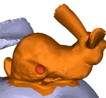
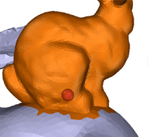
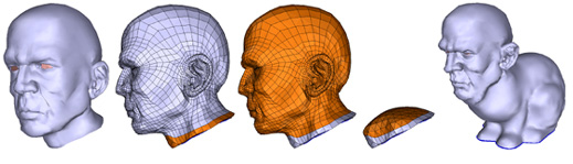
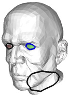
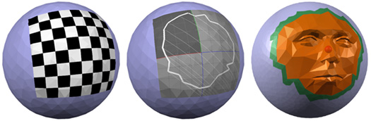
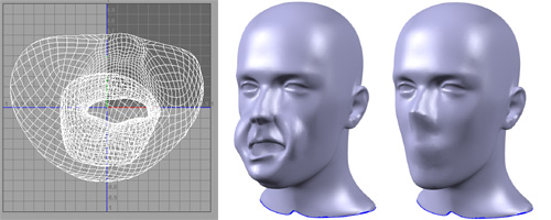
In addition to deciding on the right fill surface, you also need to make sure you are filling the right boundary loop. If you try to make a part out of a mesh with more than one boundary loop, as in the head model below, meshmixer will by default select the "longest" boundary loop. If this is incorrect, you can use the left and right arrow keys to cycle between the different boundary loops, for example selecting the eye loop in the middle image below (this will look weird when dropped...but also kind of neat).
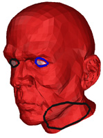
If for some reason the filling algorithm fails, or meshmixer decides that a loop is unsuitable for use as a part-merging boundary, the surface will be rendered in red.
As with selecting a part boundary, having a smooth open boundary loop will lead to better results when dropping the part. If you need to 'clean up' your boundary loop, you can select faces and then hit the x key to delete them from the mesh.
[meshmixer01]
The instructions below explain how make parts for meshmixer01. You can still use this process to make parts for meshmixer02, but it is not as robust. The section immediately below explains a bit more about how meshmixer works, which might be helpful to read if you really want to understand what is going on under the hood.
How meshmixer pastes your part
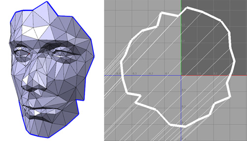
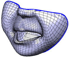
If you understand how meshmixer can take a part and stick it onto another mesh, you'll understand how to make your own parts. At least, that's the plan. So, lets look at one of the sample parts shipped with meshmixer, a face cut from a head (below-left).
There are two important things about this mesh. First, it has a boundary loop, which is highlighted blue in the image below-left. A part absolutely has to have a boundary loop - this is where meshmixer is going to stitch the part into the target mesh.
The mesh below also has UV coordinates for the boundary loop vertices. The image below-right shows the UV map for the face part, with the boundary edges highlighted in white. We see that the UV-boundary looks like an unfolded version of the 3D boundary. Note that the UVs of the interior vertices are not used.
So now we have a part mesh with a boundary loop, and that boundary loop has UV coordinates. Now when you go to drop the part, what actually happes is that meshmixer dynamically computes a local UV-map on the target surface. This is shown below-left on a sphere, where the local UV-map is displayed using a checkerboard texture. You never see this local UV-map, but it is there.
Once we have have the local UV-map, we can copy the UV-boundary of the part into this new UV-map on the target surface. In the image below-center, we can see what this would look like.
Next we transfer the 3D boundary to the surface of the sphere, using this mapping between UVs. Then we transfer the deformation of the boundary to the part interior, and stitch it into the target mesh (this is also done in the UV map). And we're finished!
Part Requirements
Now that we know how part drag-and-drop works, we can see some of the requirements. We have already discussed a few:
(1) The mesh needs a boundary loop. This is where meshmixer is going to stitch your part to the target surface. So, no closed meshes.
(2) The boundary loop needs UV coordinates, and the UV loop needs to look something like an unfolded version of the 3D loop.
There are a few other requirements, that are maybe less obvious:
(3) The UV loop needs to be centered around the origin.
(4) The UV loop needs to have a similar scale to the 3D loop. Ideally, the length of the UV loop will be the same as the length of the 3D loop. But the part will work OK as long as we are close.
(5) The UV loop needs to be free of self-intersections. This is necessary for the stitching to work properly.
Example: A Bad Part
Here I will show an example of a part that was initially broken, and how I fixed it. Here is the part mesh in 3D:
And here is the initial UV parameterization of the mesh. The right image is a close-up.
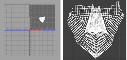
This mesh meets criteria (1) and (2) - it has an boundary loop, with UV values. But the UV loop is not centered at the origin, so requirement (3) is not met. It's hard to tell by visual inspection if the UV loop has the same scale as the 3D loop, so (4) might be OK (we'll see below that it isn't, though). I don't see any self-intersections, so (5) is OK.
We can easily translate the UV's to be centered at the origin. But the part still won't work very well. Remember, criteria (2) also says that the UV loop should "look like" the 3D loop. This is clearly not the case.
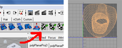
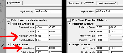
So, what to do? Well, a simple fix is to use Maya to generate UVs for the boundary using projection. I import the OBJ and then select all the faces and click the planar projection button (red arrow). This gives a better-looking UV loop (you can ignore the interior faces, as meshmixer does).
However, we see that the UV loop is still not centered around the origin. Also, Maya's planar projection tool by default scales the UVs so they fit inside the unit box. This is undesirable for criteria (4). We can fix both of these by changing parameters of the planar projection. Set the Projection Width and Projection Height to 1, and the Image Center to the origin.
Now we get a nicer projection, centered around the origin. Criteria (1) to (5) are all met, so we export the mesh from Maya, copy it into the \parts_default folder, and drop it onto a head (note that I prepped the surface a bit, shown on the right, to get a better drop).
Note that if your part has a highly curved boundary, a cylindrical or spherical projection might be more appropriate. Arguably one of these would have been better for this part, but it is harder to get the scale right. Remember that the interior UVs don't matter, only the boundary. For harder cases you might need to manually clean up the UV loop (good luck!)